From Friday, April 19th (11:00 PM CDT) through Saturday, April 20th (2:00 PM CDT), 2024, ni.com will undergo system upgrades that may result in temporary service interruption.
We appreciate your patience as we improve our online experience.
From Friday, April 19th (11:00 PM CDT) through Saturday, April 20th (2:00 PM CDT), 2024, ni.com will undergo system upgrades that may result in temporary service interruption.
We appreciate your patience as we improve our online experience.
Biosignals often contain noise. For example, an electrocardiogram (ECG) often contains power line interference. You can use adaptive filters to separate the signal you need from the original, noisy biosignal.
The Online Biosignal Noise Reduction Data Logger is an application that uses adaptive filters to reduce the noise in a noisy biosignal. This application includes the following features:
Setting Up the Online Biosignal Noise Reduction Data Logger Hardware Components
As a noise reduction application, the Online Biosignal Noise Reduction Data Logger requires signals from two channels. One channel contains the original, noisy signals. The second channel contains the noise signal, which is considered a reference. The Online Biosignal Noise Reduction Data Logger requires you to set up hardware. Setting up the hardware depends on the application you need to reduce noise.
Setting Up a Power Line Cancellation Application
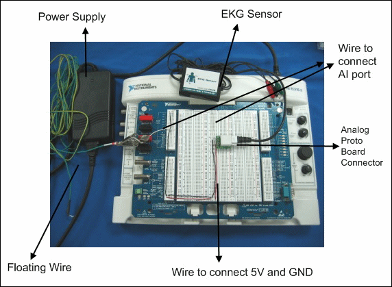
If you use a twelve-lead or three-lead ECG instrument to measure an ECG, you can use any of the leads as the original signal. For the reference signal, use the common-mode signal, which usually is recorded at the right leg reference electrode or other reference electrode. Refer to the article [1] for more information about lead and reference electrodes. For example, you can use NI ELVIS II and a third-party ECG sensor device, such as the Vernier (http://www.vernier.com) EKG Sensor, to configure a power line cancellation system.
If you use the NI ELVIS II and Vernier EKG Sensor, connect the EKG Sensor to the input of the Vernier Analog Proto Board Connector. Connect the output of the Vernier Analog Proto Board Connector to one of the NI ELVIS II AI ports. This connection obtains the original noisy biosignal.
To obtain the reference signal by using NI ELVIS II and the Vernier EKG Sensor, you can complete one of the following configurations.
After setting up the hardware components of the application, launch the Online Biosignal Noise Reduction Data Logger to configure the software components to reduce noise.
Setting Up a Fetal ECG Extraction Application
A fetal electrocardiogram (FECG), which you measure from the maternal abdomen, often contains a strong maternal electrocardiogram (ECG). You can use the Online Biosignal Noise Reduction Data Logger to extract the FECG from a noisy biosignal.
Typically, a twelve-lead ECG instrument has six chest leads and six limb leads. This applications utilizes the six chest leads in two groups. One group of leads obtains the signals for the original signal. These leads are placed on the abdomen, according to the following figure.

When choosing the exact locations of these leads, choose locations on the maternal abdomen such that a good FECG signal-to-noise ratio is obtained. That is, as if no maternal ECG is present. Refer to the book [2] for more information about lead placement for FECG extraction. The second group of leads obtains the signals for the reference signal. These leads are placed on the chest, near the thorax, according to the previous figure.
After placing the leads, verify that each lead corresponds to an AI port number on the hardware instrument, such as NI DAQ or NI ELVIS II. In the Online Biosignal Noise Reduction Data Logger, you must set one of the thorax leads as the reference signal and one of the abdominal leads as the original signal.
After setting up the hardware components of the application, launch the Online Biosignal Noise Reduction Data Logger to configure the software components to reduce noise.
Reducing Noise
Complete the following steps to reduce the noise in a noisy biosignal.
| Note You can use theto convert the log file this application saves from a .tdms file type to another file type. |
References:
[1] Thakor, N.V.; Zhu, Y.-S. 1991. "Applications of adaptive filtering to ECG analysis: noise cancellation and arrhythmia detection." IEEE Trans Biomed Eng, vol. 38: 785-794
[2] Callaerts, D.; J. Vandewalle; W. Sansen; J. Janssens; and G. Vantrappen. 1994. Acquisition and processing of the antepartum FECG. In A Critical Appraisal of Fetal Surveillance, edited by H.P. van Deijn and F.J.A. Copray. Amsterdam, The Netherlands: Elsevier Science B.V.
